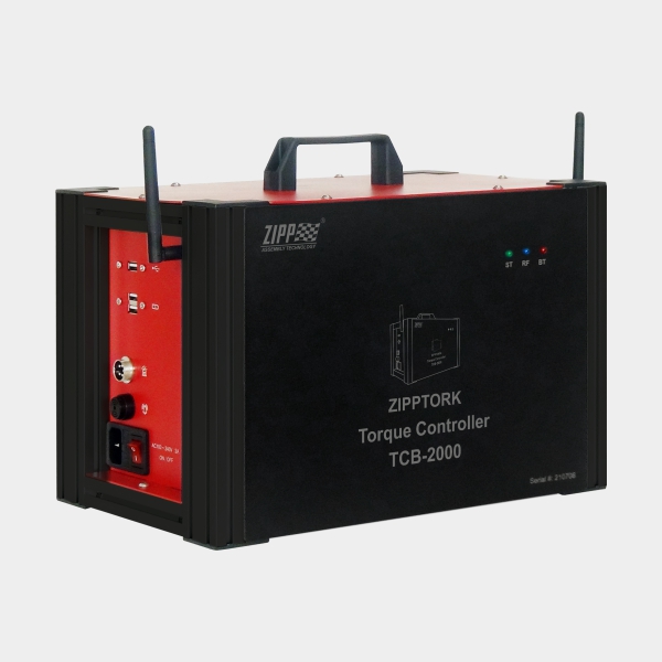
Ensuring Reliable Fastening with our patented Wireless Rotary Torque Sensor

In precision assembly, every fastening operation must deliver consistent torque to guarantee product safety, performance, and quality. Over time, however, power tools drift out of tolerance due to wear, vibration, or repeated impact. Without routine verification, this drift can compromise joint integrity and increase the risk of product failure. ZIPPTORK’s wireless rotary torque sensor provides a practical, real-time solution for validating tool calibration, measuring dynamic torque, and ensuring repeatable fastening results under actual operating conditions.


Why Dynamic Torque Measurement Matters


Unlike static torque checks, which measure fasteners after installation, dynamic torque measurement evaluates a tool while it is fastening. This approach captures the accurate torque profile under working conditions, including:


  • Operator technique and handling

  • Tool clutch performance

  • Frictional effects from lubricants, coatings, or washers

  • Joint stiffness and material behavior (hard vs. soft joints)


By simulating real-world fastening, ZIPPTORK’s wireless rotary torque sensor reveals whether a tool consistently meets specifications in the field.

How ZIPPTORK’s Wireless Rotary Torque Sensor Works


ZIPPTORK’s system integrates a wireless rotary transducer between the tool and the fastener. The sensor continuously monitors torque and angle throughout the fastening process, transmitting the data in real-time to a paired controller or software interface.

Key functions include:


  • Torque capture in real time – Records the exact torque delivered during fastening, not just at the end of the cycle.

  • Angle measurement – Tracks fastener rotation to validate that clamp force is achieved correctly.

  • Wireless data transmission – Eliminates the need for cables, making the system easier to use in production environments.

  • Shock and vibration resistance – Engineered to withstand the excessive impact of tools like air or cordless impact wrenches.


This setup effectively transforms a standard torque tool into a torque-monitored system, enabling immediate validation without slowing down production.

Conducting Routine Torque Verification with ZIPPTORK


With the wireless rotary torque sensor, a torque audit can be performed quickly and accurately:


  1. Select representative joints from the production line.

  2. Attach the rotary torque sensor between the tool and fastener.

  3. Tighten the fastener under normal conditions, letting the sensor capture dynamic torque and angle data.

  4. Review readings instantly via the paired ZIPPTORK controller or software.

  5. Compare results with specifications to verify calibration and repeatability.


This process can be repeated as part of a daily torque audit or scheduled preventive maintenance, ensuring tools stay within tolerance.

Data Collection and Torque Analysis


ZIPPTORK’s system does more than measure torque—it also provides a platform for data-driven quality control:


  • Record and store torque readings from multiple fastening cycles.

  • Plot torque trends to identify tool wear or operator variability.

  • Apply statistical process control (SPC) methods, such as Cp/Cpk analysis, to confirm process capability.

  • Maintain traceable records for audits and compliance.


By analyzing torque data, manufacturers can accurately predict tool maintenance needs, minimize unplanned downtime, and ensure consistent quality throughout the assembly process.


Best Practices with ZIPPTORK’s Wireless Torque System


  • Audit tools regularly (daily, weekly, or based on cycle counts).

  • Always test under real joint conditions—hard joint simulators alone don’t reflect field performance.

  • Combine torque + angle analysis for a more accurate assessment of clamp load.

  • Train operators to use tools consistently, minimizing variability.

  • Use stored torque data as part of a preventive maintenance program.


ZIPPTORK’s wireless rotary torque sensor simplifies calibration verification, captures real-time torque and angle under dynamic conditions, and provides actionable data for continuous process improvement. By integrating this tool into routine quality control, manufacturers can ensure their fastening processes remain accurate, repeatable, and reliable—reducing risk, avoiding costly rework, and guaranteeing the integrity of every joint.

Turn Any Air Impact Wrench Into a Torque Controlled Tool with ZIPPTORK

TCB Air Pneumatic Torque tool controller

ZIPPTORK’s torque controller upgrades a standard pneumatic impact wrench into a torque-controlled fastening tool delivering ±10% to ±15% accuracy (joint-dependent). It closes the historical gap between “roughing” with impacts and “controlling” with expensive, high-maintenance pulse or DC tools. Paired with an integrated wireless torque transducer, ZIPPTORK captures every tightening—time, torque curve, angle, and result—so you can monitor, trace, and improve your bolting process without replacing your existing air tools.


Why control torque on an impact wrench?


Traditional impact wrenches are fast and rugged, but they’re open-loop: operators “feel” or “count hits,” which leads to scatter, rework, and weak traceability. Pulse tools improve control, but they also come with higher costs, increased hydraulic maintenance, and more downtime. ZIPPTORK adds closed-loop control and digital traceability to the impact tool you already own.


How ZIPPTORK works


  1. Measure
    A compact wireless torque transducer sits in the load path (socket, inline, or adapter form factor). It streams high-rate torque and angle data during each hit.

  2. Model
    ZIPPTORK’s controller builds an adaptive model of the joint: it distinguishes rundown, snug point, yield tendency, and prevailing torque. It learns the joint rate (hard/soft) and compensates in real time.

  3. Control
    Using the model, the controller manages air flow and impact energy—modulating air to the motor and making a go/no-go decision on additional blows. It stops the tool precisely when the target torque window is reached.

  4. Verify
    The controller validates the achieved torque against the target and tolerance. If the last impact overshoots or undershoots, it flags the cycle and can automatically allow or block a corrective pulse within limits.

  5. Record
    The full torque-time-angle signature is stored and transmitted to your line system (e.g., MES/QMS). Each cycle is traceable by part, VIN/serial, station, operator, tool, and timestamp.


Accuracy: ±10% to ±15%—what it means and how you get it


ZIPPTORK delivers ±10% to ±15% torque accuracy on appropriately selected joints and tools by combining:

  • High-rate sensing of the dynamic torque peak during impact.

  • Joint characterization (hard vs. soft) and adaptive shutoff.

  • Controlled re-hit logic with decaying energy to “sneak up” on the target.

  • Calibration workflow using a reference transducer on a test joint.


Best practices to hit the tighter end (±10%)


  • Use a well-matched impact size for the torque range (avoid oversized tools).

  • Keep air supply stable (regulated pressure, adequate hose ID, minimal drops).

  • Set joint-specific programs (target, window, re-hit count, max time).

  • Validate with a daily check on a master joint or torque analyzer.

  • Maintain sockets/adapters; worn interfaces add scatter.


Note: Extremely soft joints, heavy prevailing torque, or highly elastic stack-ups may trend toward the ±15% end. ZIPPTORK detects these and applies the right control strategy while flagging cycles that exceed capability limits.

Replace pulse tools without their headaches.

AspectOil Pulse WrenchImpact + ZIPPTORK
Capital costHighUse existing impact + controller
MaintenanceHydraulic fluid changes, seals, and downtimeStandard pneumatic upkeep
SpeedFastFast (impact cadence)
AccuracyGenerally good±10%–±15% with adaptive control
Reaction forceLowLow (impacts)
TraceabilityOften optionalStandard: full cycle data
FlexibilityModel-specificWorks with many air impacts

With ZIPPTORK, you retain the speed and durability of impacts while gaining process control and traceability—often at a fraction of the lifecycle cost of pulse systems.


Integrated wireless torque transducer = complete traceability


  • What’s captured per tightening: part ID, program, final torque, angle (if applicable), OK/NOK, peak torque, rundown time, number of blows, re-hit count, operator ID, station ID, timestamp.

  • Live monitoring: dashboards for yield, Cpk, and alarms (e.g., tool drift, unstable joints).

  • Connectivity: edge gateway or direct API to your MES/QMS; local buffering prevents data loss.

  • Analytics: compare torque curves across lots, spot cross-threading, worn fasteners, lubrication changes, or operator technique issues.


Implementation workflow


  1. Application study
    Define torque range, joint type (hard/soft, prevailing torque), cycle time, ergonomics, and quality requirements.

  2. Tool pairing
    Match your current impact wrenches to ZIPPTORK programs; verify sockets/adapters and the wireless transducer form factor.

  3. Baseline & calibration
    Run a capability set on a master joint with a reference analyzer. Create target/tolerance windows and re-hit rules.

  4. Pilot run
    Deploy at one station, log results, and tune shutoff thresholds and air regulation.

  5. Scale-up
    Roll out programs to multiple stations; train operators on visual cues and NOK handling.

  6. Sustain
    Daily check on a master joint, weekly air line audit, and monthly program review using collected data.


Where ZIPPTORK shines


  • Automotive & off-road assembly: chassis, suspension, subframe, and service joints where speed matters but traceability is now required.

  • White goods & general industry: sheet-metal fasteners, frame assemblies, large fixtures.

  • Field service & repair cells: portability with data capture for regulated or warranty-critical work.


Safety, ergonomics, and quality


  • Low reaction torque: impacts transmit little steady reaction, reducing operator strain versus stall tools.

  • Fewer re-hits: precise shutoff lowers vibration exposure and noise compared to “free-running” impacts.

  • Poka-yoke: program-based interlocks (wrong program, missing data, out-of-window torque) prevent pass-through of bad assemblies.

  • Clear OK/NOK feedback: bright indicators and audible signals shorten decision time.


Limitations & how ZIPPTORK addresses them


  • Very soft or springy joints can degrade accuracy; consider using a multi-stage rundown with controlled re-hits or revisiting joint design.

  • High prevailing torque (locking nuts, inserts): set angle-over-torque criteria and monitor the curve shape to avoid misreads.

  • Tool health drift: caught by trend alarms and daily checks; swap sockets and verify balance.

  • RF-noisy environments: buffered logging prevents data loss; verify coverage during commissioning.


ROI snapshot


  • Lower capital costs by reusing existing impacts.

  • Less maintenance than hydraulic pulse systems.

  • Scrap/rework reductions from controlled, traceable torque.

  • Audit-ready records for customers and regulators.

  • Faster changeovers with saved joint programs.


Getting the most from ZIPPTORK


  • Stable, regulated air supply and correct hose ID

  • Correct impact size for torque target

  • Fresh, accurate calibration on a master joint

  • Joint-specific programs (targets, windows, re-hit policy)

  • Operator training on OK/NOK, retorque rules

  • Daily verification & periodic capability review


ZIPPTORK turns the impact wrench you already trust into an innovative, torque-controlled, data-logging solution. Expect ±10–15% accuracy, full traceability, and lower lifecycle costs compared with oil pulse tools—without sacrificing speed or durability. If you need modern process control and proof of compliance, ZIPPTORK is the most direct path to get there.

5 Types of Motors for Automation Applications

Motor solutions are essential for many applications, powering automation systems. Although every automated system varies, there are numerous motor types tailored to meet each specific need. With countless options in brands and sizes, choosing the right motor is crucial.


1. AC Motors


AC motors transform electrical energy into mechanical motion by transmitting alternating current over long distances. They are known for their flexibility, efficiency, and quiet operation, making them suitable for pumps, fans, blowers, and other systems that require constant, variable, or adjustable speeds.


Fundamentally, AC motors consist of a stator and a rotor, both of which contain conductors. The motor spins the conductor in a magnetic field, generating voltage. If the conductor is in a closed circuit, it produces current.


Manufacturers select AC motors for several reasons:


– High efficiency: They offer a good balance of speed and torque without overheating.
– Brushless design: This reduces friction and heat and extends lifespan.
– Quiet operation: They produce minimal humming sounds.
– Simplicity and versatility: With only one moving part, they come in various shapes and power outputs to fit many applications.
– Speed control: Adjusting the frequency changes the motor’s speed.


2. Brushed DC Motors


Brushed DC motors are suited for applications needing high peak torque and simple speed control. They are cost-effective, easy to control, and feature a linear torque-speed relationship.


These motors include a stator, rotor, brushes, and a commutator. They operate with permanent magnets outside the motor, creating an electromagnetic field. Their ability to produce high torque during start-up and stopping makes them ideal for applications such as dispensing, packaging, and some robotics.


However, they suffer from mechanical wear on the brushes and commutator, reducing their lifespan. Still, their low initial cost can offset this drawback.


3. Brushless DC Motors


Similar in function to brushed DC motors, brushless variants operate without brushes, with magnets inside the rotor instead of outside.


They are quieter, more efficient, and last longer than brushed motors. They run continuously with less heat and are suitable for environments with dust, grease, or oil. The trade-off is a slightly higher initial cost.


4. Geared DC Motors


These motors feature a gear assembly that increases torque and reduces speed, a mechanism known as gear reduction.


They work with gearboxes, tend to be compact, and deliver a high torque relative to their size.


5. Servo Motors


Servo motors transform rotary motion into linear motion and are equipped with feedback devices such as encoders or resolvers. They provide detailed data on position and velocity and require controllers for precise operation, making them ideal for robotics and industrial automation.


Most modern servo motors are brushless, offering accuracy, reliability, and suitability for harsh conditions. Features include high acceleration, quiet operation, and closed-loop control, with a high torque-to-inertia ratio similar to that of AC motors. The main disadvantage is their higher initial cost.


Applications include robotics, conveyor systems, metalworking machines, printing presses, CNC equipment, and packaging lines.

This site uses cookies to offer you a better browsing experience. By browsing this website, you agree to our use of cookies.